
 EN
EN



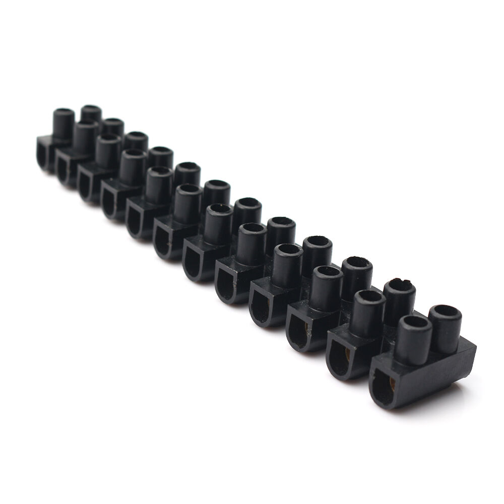
Wire terminals are essential components in electrical connections across industrial, automotive, and commercial applications, serving as the critical interface between conductors and equipment. Despite their apparent simplicity, improper installation of wire terminals remains one of the most frequent causes of electrical failures, equipment downtime, and safety hazards in professional environments. Understanding and avoiding common installation errors is not merely a matter of technical proficiency but a fundamental requirement for ensuring system reliability, operational safety, and long-term performance in demanding applications where connection integrity directly impacts productivity and risk management.
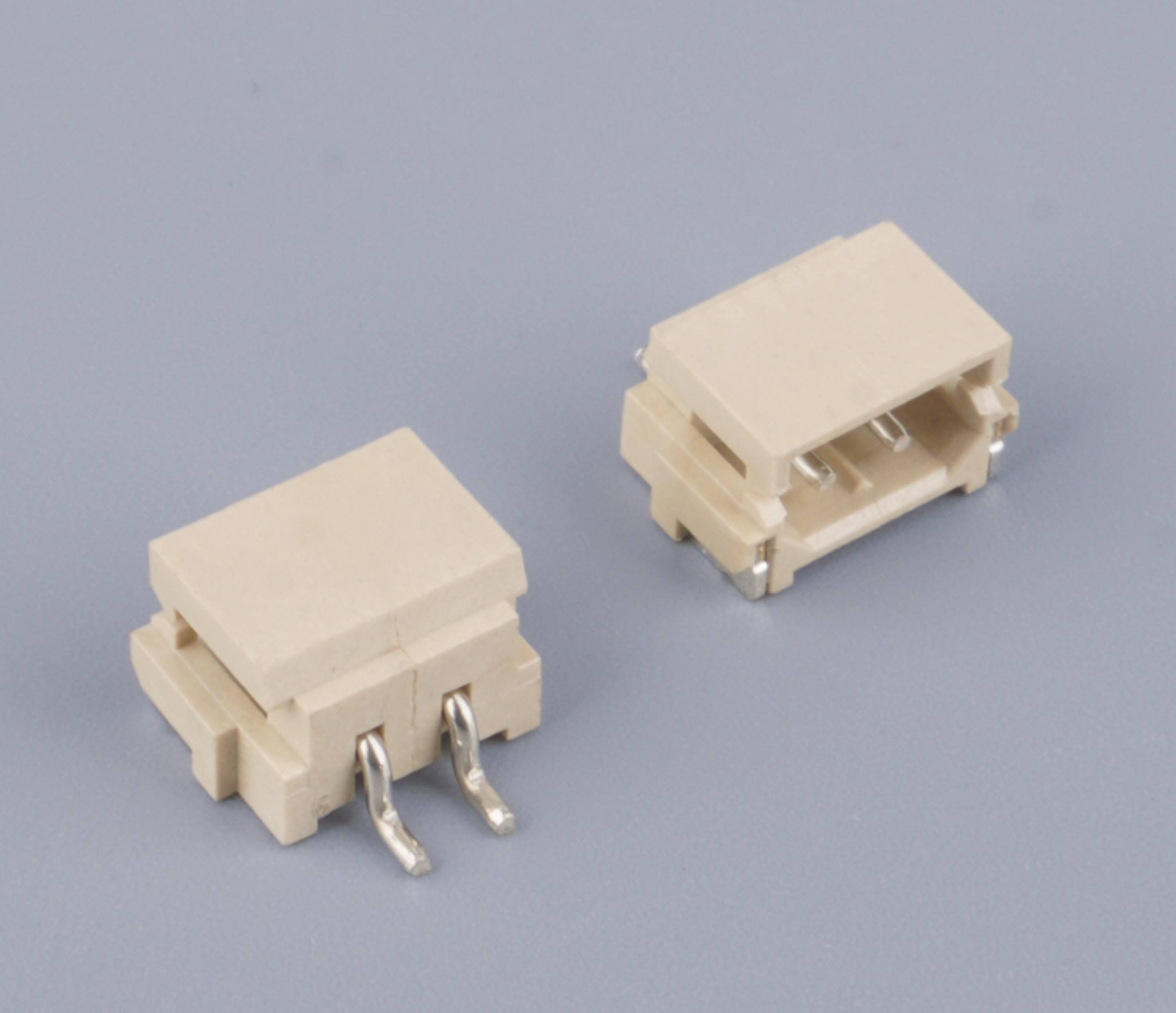
Professional electricians, maintenance technicians, and industrial installers recognize that the majority of terminal-related failures originate not from component defects but from preventable installation mistakes that compromise the mechanical and electrical properties of the connection. These errors range from basic oversights in wire preparation to subtle miscalculations in crimping force, each capable of creating resistance hotspots, mechanical weakness, or premature failure under operational stress. This comprehensive examination identifies the most critical installation mistakes associated with wire terminals, explains why these errors occur in real-world scenarios, and provides actionable guidance for establishing installation practices that consistently deliver reliable, code-compliant connections across diverse application environments.
Critical Wire Preparation Errors That Compromise Terminal Performance
Inadequate Wire Stripping Length and Technique
One of the most fundamental yet frequently overlooked mistakes when installing wire terminals involves improper wire stripping, where technicians either remove excessive insulation or leave insufficient conductor exposure for proper terminal engagement. When too much insulation is removed, exposed conductor extends beyond the terminal barrel, creating shock hazards, short-circuit risks, and increased vulnerability to environmental contamination that accelerates corrosion. Conversely, insufficient stripping leaves insulation within the crimp zone, preventing proper metal-to-metal contact and creating high-resistance connections that generate heat under load, ultimately leading to connection failure and potential fire hazards in power distribution applications.
The consequences of incorrect stripping extend beyond immediate electrical concerns to affect the mechanical integrity of wire terminals throughout their service life. Excessive conductor exposure subjects bare copper or aluminum to oxidation, particularly in humid or chemically aggressive environments common in industrial facilities, while insulation trapped in the crimp zone prevents the terminal from achieving the necessary compression ratio for reliable mechanical retention. Professional installation standards specify precise stripping dimensions typically ranging from eight to twelve millimeters depending on terminal design, yet field observations consistently reveal significant deviations from these specifications, often resulting from inadequate training, worn stripping tools, or time-pressure compromises that sacrifice quality for speed in high-volume installation scenarios.
Conductor Damage During Preparation Process
Wire terminals require undamaged conductors to achieve their rated current capacity and mechanical strength, yet preparation processes frequently introduce nicks, cuts, or strand breakage that substantially reduce effective conductor cross-section and create stress concentration points. Dull or improperly adjusted wire strippers commonly score individual strands in stranded conductors, reducing the effective ampacity and creating weak points where mechanical stress concentrates during vibration or thermal cycling. In solid conductor applications, even minor surface damage from stripping tools creates crack initiation sites that propagate under mechanical stress or thermal expansion cycles, eventually leading to conductor fracture and complete connection failure.
The impact of conductor damage becomes particularly critical in applications involving wire terminals subjected to vibration, thermal cycling, or mechanical stress, where compromised strands act as fatigue crack initiators. Studies of field failures consistently identify conductor damage during preparation as a contributing factor in premature terminal failures, particularly in automotive, railway, and heavy equipment applications where vibration exposure is continuous. Prevention requires not only proper tool selection and maintenance but also systematic inspection protocols that verify conductor integrity before terminal application, yet such verification steps are frequently omitted in production environments where installation speed takes priority over quality assurance measures that could prevent costly downstream failures.
Improper Wire End Preparation for Terminal Type
Different wire terminals require specific conductor end configurations for optimal performance, yet installers frequently apply standardized preparation methods without considering terminal-specific requirements. Stranded conductors intended for crimp barrel terminals must maintain tight strand bundling without fraying or separation, while some terminal designs require pre-twisting to prevent strand protrusion during crimping. Failure to twist stranded conductors before insertion into wire terminals commonly results in stray strands that escape the crimp zone, creating short-circuit hazards and reducing the effective contact area within the terminal barrel, thereby increasing connection resistance and heat generation under operational loads.
The preparation requirements become more complex when dealing with fine-strand or extra-flexible conductors specifically designed for applications requiring repeated flexing or minimal bend radius. These specialized conductors may require ferrule application before insertion into certain terminal types to prevent strand separation and ensure uniform current distribution across all conductor elements. Installing wire terminals on such conductors without appropriate end treatment frequently results in uneven crimping where some strands experience excessive compression while others remain insufficiently engaged, creating connections with unpredictable electrical characteristics and reduced mechanical reliability that manifest as intermittent failures difficult to diagnose in operational systems.
Crimping Tool Selection and Application Mistakes
Using Incorrect or Non-Specific Crimping Tools
Perhaps the most consequential error in wire terminals installation involves using improper crimping tools, including general-purpose pliers, diagonal cutters, or non-terminal-specific crimpers that cannot deliver the precise compression geometry required for reliable connections. Wire terminals depend on carefully controlled deformation that achieves specific compression ratios, indent patterns, and metal flow characteristics that only purpose-designed crimping tools can provide. General hand tools create irregular compression with inconsistent pressure distribution, frequently resulting in over-crimped regions where conductor strands fracture and under-crimped zones where insufficient contact pressure produces high-resistance connections that fail prematurely under operational stress and thermal cycling.
The technical requirements for proper terminal crimping extend beyond simple compression force to include precise die geometry that forms specific crimp profiles, whether hexagonal, indent, or other configurations specified by terminal manufacturers. Each terminal design requires matching dies that produce the correct compression pattern, yet field installations frequently involve using whatever crimping tool is available rather than the specified tooling for the particular wire terminals being installed. This tool mismatch problem becomes particularly acute in multi-vendor environments where different terminal suppliers specify different crimp configurations, requiring technicians to maintain tool inventories and reference documentation that are often unavailable during actual installation work, leading to compromises that sacrifice connection quality for installation convenience.
Incorrect Tool Adjustment and Calibration
Even when using appropriate crimping tools specifically designed for wire terminals, incorrect adjustment or lack of calibration verification represents a critical installation mistake that compromises connection quality. Adjustable ratchet crimpers require proper setting for the specific wire gauge and terminal size combination, with settings that vary based on conductor material, stranding configuration, and terminal barrel dimensions. Operating these tools without verification of proper adjustment commonly produces either insufficient compression that fails to achieve the required cold-weld effect between conductor and terminal, or excessive compression that fractures conductor strands and reduces current-carrying capacity below safe operational thresholds.
The calibration status of crimping tools directly affects the consistency and reliability of wire terminals installations, yet systematic tool verification remains uncommon in many professional environments. Hydraulic and pneumatic crimpers require periodic calibration to ensure they deliver specified compression forces across their operational range, while mechanical ratchet tools experience wear that gradually changes their crimp characteristics over thousands of cycles. Failure to implement regular tool inspection and calibration programs results in progressive drift in crimp quality that may not produce immediately obvious failures but creates populations of marginally acceptable connections with reduced service life and increased vulnerability to environmental stress, vibration, and thermal cycling that eventually manifest as field failures requiring costly remediation.
Incomplete Crimp Cycle and Position Errors
Ratchet-type crimping tools designed for wire terminals incorporate mechanisms that prevent premature tool release before completing the full compression cycle, yet technicians occasionally override these safety features or fail to ensure complete crimping action. Partial crimps that do not achieve full die closure create connections with inadequate compression, irregular contact pressure distribution, and mechanical retention far below rated values. These incomplete crimps may initially function adequately under light loads but rapidly deteriorate when subjected to vibration, thermal cycling, or sustained high-current operation, leading to increased contact resistance, localized heating, and eventual connection failure that may create safety hazards in critical power distribution or control circuits.
Positioning errors during crimping represent another common mistake where wire terminals are not properly aligned in the crimping dies before tool actuation. Misalignment causes asymmetric compression that concentrates stress on one side of the terminal barrel while leaving the opposite side inadequately compressed, resulting in uneven current distribution and mechanical weakness. The conductor must be fully inserted to the barrel stop before crimping, yet visual verification of proper insertion is frequently omitted in production environments, particularly when installing insulated wire terminals where the vinyl sleeve obscures the metal barrel. This oversight commonly produces crimps on the conductor insulation rather than the stripped conductor itself, creating purely mechanical connections with no actual electrical contact and extremely high resistance that generates heat and eventual failure.
Terminal Selection and Application Specification Errors
Incorrect Wire Gauge to Terminal Size Matching
Matching wire terminals to conductor size represents a fundamental requirement for reliable connections, yet size mismatches remain surprisingly common in field installations. Oversized terminals applied to smaller conductors fail to achieve adequate compression even with proper crimping tools, resulting in loose mechanical retention and poor electrical contact that creates high-resistance connections prone to overheating. The excessive space within an oversized terminal barrel prevents proper cold-welding between conductor and terminal material, while inadequate compression allows relative movement between components during vibration or thermal expansion, accelerating wear and eventual connection failure through fretting corrosion that progressively degrades contact quality.
Conversely, attempting to force undersized terminals onto larger conductors represents an equally problematic error that prevents proper conductor insertion and crimping. When wire gauge exceeds terminal capacity, conductors cannot fully seat within the barrel, resulting in partial insertion crimps that engage only a portion of the conductor cross-section. These improper connections exhibit dramatically increased electrical resistance, severely reduced mechanical strength, and extreme vulnerability to pull-out failure under even modest mechanical stress. The problem intensifies in applications involving wire terminals on stranded conductors where size mismatch causes strand compression and deformation during insertion, preventing proper seating and creating irregular current distribution patterns that concentrate heating in specific regions of the connection interface.
Material Compatibility Oversights
Wire terminals are manufactured from various materials including copper, tinned copper, aluminum, and specialized alloys, each designed for specific conductor materials and environmental conditions. Installing terminals without consideration of material compatibility creates galvanic corrosion risks when dissimilar metals contact in the presence of moisture, leading to progressive connection degradation. Copper terminals applied to aluminum conductors without proper transition compounds or barrier plating create electrochemical cells that accelerate oxidation at the interface, increasing resistance and generating heat that further accelerates the corrosion process until complete connection failure occurs, often manifested as overheating, discoloration, or even fire initiation in power distribution applications.
The material selection for wire terminals must also account for environmental exposure including temperature extremes, chemical contamination, and moisture conditions. Standard copper terminals perform adequately in controlled indoor environments but corrode rapidly when exposed to marine atmospheres, chemical processing environments, or outdoor installation sites without adequate protection. Tinned or nickel-plated terminals provide enhanced corrosion resistance but may require different crimping parameters to achieve proper compression through the plating layer. Failure to specify appropriate terminal materials for the intended service environment creates connections that deteriorate prematurely, requiring costly maintenance interventions and creating reliability concerns in critical systems where connection failure could produce safety hazards or operational shutdowns.
Insulation Support and Strain Relief Neglect
Quality wire terminals incorporate insulation support features including vinyl sleeves, heat-shrink components, or mechanical strain relief elements designed to prevent stress concentration at the conductor-terminal interface. Neglecting to properly position or crimp these support features represents a critical installation error that accelerates fatigue failure in applications involving vibration or repeated flexing. The insulation crimp barrel must fully engage the conductor insulation jacket to provide mechanical support that prevents bending stress from concentrating at the transition point between rigid terminal and flexible conductor, yet installers frequently focus exclusively on the conductor crimp while ignoring or improperly forming the insulation support crimp.
The consequences of inadequate strain relief become particularly severe in applications where wire terminals connect to moving components, vibrating equipment, or installations subject to thermal expansion cycling. Without proper insulation support, mechanical stress concentrates at the conductor-terminal junction, causing progressive strand breakage in stranded conductors or fatigue crack propagation in solid conductors. This failure mechanism typically develops gradually over extended service periods, making root cause identification difficult when failures eventually occur. Professional installation standards for wire terminals in vibration-prone applications specify additional strain relief measures including cable securing within specified distances from terminal connections, yet these requirements are frequently overlooked in field installations where immediate functional testing shows no problems, masking developing reliability issues that will manifest only after extended operational exposure.
Environmental Protection and Installation Context Mistakes
Inadequate Moisture and Contamination Protection
Wire terminals installed without appropriate environmental protection rapidly deteriorate when exposed to moisture, dust, chemical vapors, or other contaminants common in industrial and outdoor environments. While insulated terminals provide basic protection against direct electrical contact, the vinyl sleeves typically used on standard wire terminals offer minimal resistance to moisture ingress, particularly after thermal cycling creates microscopic cracks in the insulation material. Moisture penetrating the conductor-terminal interface initiates corrosion processes that increase connection resistance and reduce mechanical strength, eventually producing overheating or mechanical failure depending on the specific application demands and exposure severity.
Professional installations in harsh environments require supplementary protection measures including heat-shrink tubing with adhesive liners, conformal coatings, or complete enclosure within sealed junction boxes, yet these protections are frequently omitted due to cost pressures or schedule constraints. The long-term consequences of inadequate environmental protection may not appear immediately but accumulate progressively as repeated wetting and drying cycles concentrate contaminants and accelerate electrochemical degradation. Applications involving wire terminals in marine environments, chemical processing facilities, or outdoor exposed installations require particularly rigorous protection strategies including stainless steel or specially coated terminals combined with sealed enclosures and proper drainage provisions, yet field installations frequently apply standard indoor-rated components and protection methods inadequate for the actual service environment.
Improper Torque Application on Mechanical Fasteners
Ring and spade type wire terminals rely on mechanical fasteners to create electrical contact and mechanical retention at connection points, yet improper torque application during installation represents a common error that compromises connection quality. Insufficient torque fails to compress the terminal adequately against the contact surface, creating high contact resistance that generates heat and allows oxidation to develop between mating surfaces. This under-torqued condition also permits relative movement under vibration, causing fretting wear that progressively degrades electrical contact and mechanical retention. The problem intensifies in high-current applications where inadequate contact pressure cannot dissipate resistive heating, creating accelerating degradation cycles that eventually produce connection failure.
Excessive torque application creates equally serious problems by deforming wire terminals beyond their elastic limit, causing permanent damage that reduces effective contact area and may crack terminal materials. Over-torquing also risks conductor damage within the crimped barrel, particularly with stranded conductors where excessive mechanical stress can fracture individual strands, reducing current capacity and creating localized heating. Each terminal size and material combination requires specific torque values to achieve optimal contact pressure without mechanical damage, yet field installations frequently apply torque based on installer experience or feel rather than verified torque specifications. This inconsistency creates variable connection quality across installations, with some connections under-torqued and vulnerable to vibration loosening while others are over-torqued and mechanically compromised, both conditions reducing system reliability and creating latent failure risks.
Neglecting Temperature Rise and Current Capacity Verification
Wire terminals have specific current ratings based on conductor size, terminal material, and connection quality, yet installations frequently proceed without verification that terminal selection and installation quality can safely handle anticipated current loads. Even properly installed terminals experience temperature rise during high-current operation, with the magnitude depending on connection resistance, ambient temperature, and heat dissipation capability. Failure to account for these thermal factors leads to terminal selection that appears adequate based on conductor ampacity calculations but operates at excessive temperatures that accelerate insulation degradation, increase oxidation rates, and reduce connection reliability over time.
The thermal performance of wire terminals becomes particularly critical in applications involving enclosed spaces, elevated ambient temperatures, or sustained high-current operation where temperature rise accumulates without adequate cooling. Professional engineering practices require derating terminal current capacity based on ambient temperature, bundling effects, and enclosure restrictions, yet field installations commonly apply catalog ratings without adjustment for actual operating conditions. This oversight creates connections that function initially but experience progressive degradation as sustained thermal stress accelerates oxidation, anneals conductor materials, and degrades insulation properties. The resulting failures may not occur for months or years after initial installation, making cause-effect relationships difficult to establish and creating recurring maintenance problems that could have been prevented through proper thermal analysis during initial terminal selection and installation planning.
Quality Verification and Documentation Failures
Omitting Post-Installation Inspection and Testing
Comprehensive quality assurance for wire terminals installations requires systematic inspection and testing to verify proper crimp formation, mechanical retention, and electrical continuity before systems enter service. Visual inspection should confirm complete die closure, proper crimp position, absence of conductor damage or strand protrusion, and correct positioning of insulation support features. Mechanical pull testing at specified force levels verifies crimp retention strength meets minimum requirements, while electrical resistance measurements confirm low-resistance connections appropriate for the conductor size and material. Despite the critical importance of these verification steps, field installations frequently proceed directly from crimping to system integration without any quality checks, creating latent defects that manifest as operational failures.
The economic pressure to maximize installation productivity often leads to elimination of inspection and testing protocols, particularly in competitive bidding environments where cost control takes priority over quality assurance. However, the long-term costs of field failures, emergency repairs, and potential safety incidents far exceed the modest investment required for systematic quality verification during initial installation. Advanced quality programs implement statistical sampling plans where representative samples from each installation batch undergo destructive testing to verify crimp quality, supplemented by non-destructive testing of all critical connections in safety-related or high-reliability applications. Resistance to implementing such programs typically reflects inadequate understanding of the failure costs and liability risks associated with defective wire terminals installations rather than legitimate technical or economic constraints.
Inadequate Installation Documentation and Traceability
Professional installations require documentation that records terminal types, conductor specifications, crimping tool identification, installer credentials, and inspection results for each connection or connection batch. This documentation enables traceability when problems arise, supports systematic quality improvement through failure analysis, and provides evidence of proper installation practices for regulatory compliance and liability protection. Despite these clear benefits, wire terminals installations commonly proceed with minimal or no documentation, leaving no record of what components were installed, which tools and techniques were used, or whether any quality verification occurred. This documentation gap severely hampers troubleshooting when failures occur and prevents systematic root cause analysis that could identify recurring installation errors and drive corrective training or process improvements.
The challenge of maintaining adequate installation documentation intensifies in complex projects involving multiple installation teams, extended construction periods, and thousands of individual terminal connections. Without systematic documentation protocols integrated into work processes, even well-intentioned quality efforts fail to capture essential information needed for long-term system management. Modern approaches incorporate mobile documentation tools that allow installers to record connection details, capture images of critical installations, and upload data to central databases that support later analysis and maintenance planning. However, implementation of such systems requires organizational commitment to quality management that extends beyond simple compliance with minimum installation standards to embrace continuous improvement philosophies that view documentation as a valuable asset rather than an administrative burden.
Failure to Implement Lessons Learned and Continuous Improvement
Organizations that consistently achieve high-quality wire terminals installations implement systematic processes for capturing lessons learned from both successes and failures, analyzing root causes of installation defects, and translating findings into improved training, procedures, and quality control measures. This continuous improvement approach treats each installation project as an opportunity to refine techniques and prevent recurrence of known error patterns. Conversely, organizations that repeatedly experience similar terminal installation problems typically lack mechanisms for systematic failure analysis and knowledge transfer, resulting in recurring mistakes that persist despite accumulated experience. The absence of feedback loops between field experience and training content ensures that new installers continue making the same errors that have caused problems for years.
Implementing effective continuous improvement for wire terminals installations requires commitment from technical leadership to invest time and resources in analyzing failures, documenting root causes, and developing targeted corrective measures rather than treating each incident as an isolated problem. This systematic approach identifies patterns such as specific terminal types prone to installation errors, tool maintenance issues that affect crimp quality, or training gaps that leave installers unprepared for particular challenges. The resulting improvements might include enhanced visual aids in training materials, modified tool selection for specific terminal types, or supplementary inspection steps targeting known error patterns. Organizations that embrace this continuous improvement philosophy gradually develop institutional knowledge and installation capabilities that substantially exceed industry norms, translating into enhanced reliability, reduced failure costs, and competitive advantages in markets where system dependability creates significant customer value.
FAQ
What is the most common mistake when installing wire terminals that leads to connection failure?
The most prevalent mistake involves using improper crimping tools or techniques that fail to achieve the correct compression geometry required for reliable mechanical and electrical connection. General-purpose pliers or non-specific crimpers cannot deliver the precise compression ratio and indent pattern that purpose-designed terminal crimpers provide, resulting in connections with inadequate contact pressure, poor mechanical retention, and high electrical resistance. This fundamental error creates terminals that may appear acceptable visually but lack the cold-weld effect between conductor and terminal material necessary for long-term reliability, particularly under conditions involving vibration, thermal cycling, or sustained high-current operation. Professional installations require matched crimping tools specifically designed for the terminal type being installed, with proper adjustment for wire gauge and terminal size to ensure consistent quality across all connections.
How can I verify that wire terminals have been properly installed before putting equipment into service?
Comprehensive verification of wire terminals installation quality requires multiple assessment methods including visual inspection, mechanical pull testing, and electrical continuity measurement. Visual inspection should confirm that crimp indents show complete die closure, the crimp is positioned correctly on the conductor rather than on insulation, no conductor strands protrude from the terminal barrel, and insulation support features are properly formed. Mechanical pull testing at forces specified by terminal manufacturers verifies that crimp retention strength meets minimum requirements, typically requiring specialized pull-test equipment calibrated to apply controlled force while measuring displacement. Electrical testing using low-resistance ohmmeters or milliohm meters confirms that connection resistance falls within acceptable limits for the conductor size and material, with measurements taken immediately after installation to establish baseline values for future comparison during maintenance inspections.
Are there specific wire terminals types more prone to installation errors than others?
Insulated wire terminals with vinyl sleeves present particular installation challenges because the insulation obscures visual verification of proper conductor insertion depth within the metal barrel, increasing the risk of crimping on insulation rather than bare conductor. Small-gauge terminals designed for fine conductors require precise stripping dimensions and careful handling to prevent conductor damage, while larger terminals for heavy-gauge conductors demand significant crimping force that may exceed the capability of manual tools, leading installers to use improper hydraulic tools or make multiple crimp attempts that compromise connection quality. Terminals with separate conductor and insulation crimp points require proper sequencing and positioning in multi-indent crimping tools, creating opportunities for errors that leave one or both crimps improperly formed. Heat-shrink terminals add complexity by requiring proper heat application after mechanical crimping, with inadequate heating leaving the adhesive liner unsealed and excessive heating potentially damaging conductor insulation or terminal materials.
When should wire terminals be replaced rather than reused during equipment maintenance or modifications?
Wire terminals should be considered single-use components that must be replaced rather than reused whenever connections are disassembled for maintenance, modification, or repair activities. The crimping process permanently deforms both the terminal barrel and conductor, creating a cold-weld joint that cannot be reversed without damaging one or both components. Attempting to remove and reuse crimped terminals typically requires cutting away the crimp, which damages conductor strands and reduces effective wire gauge, while any terminal that has been crimped once has undergone work-hardening that changes its mechanical properties and makes it unsuitable for re-crimping. Even in applications using bolted ring or spade terminals where mechanical disassembly is possible without terminal damage, the mating surfaces may have oxidized during service, requiring surface preparation before reinstallation to ensure adequate electrical contact. The modest cost of replacement terminals is trivial compared to the reliability risks and potential failure costs associated with reusing components designed for single installation cycles.
Table of Contents
- Critical Wire Preparation Errors That Compromise Terminal Performance
- Crimping Tool Selection and Application Mistakes
- Terminal Selection and Application Specification Errors
- Environmental Protection and Installation Context Mistakes
- Quality Verification and Documentation Failures
-
FAQ
- What is the most common mistake when installing wire terminals that leads to connection failure?
- How can I verify that wire terminals have been properly installed before putting equipment into service?
- Are there specific wire terminals types more prone to installation errors than others?
- When should wire terminals be replaced rather than reused during equipment maintenance or modifications?

