
 EN
EN



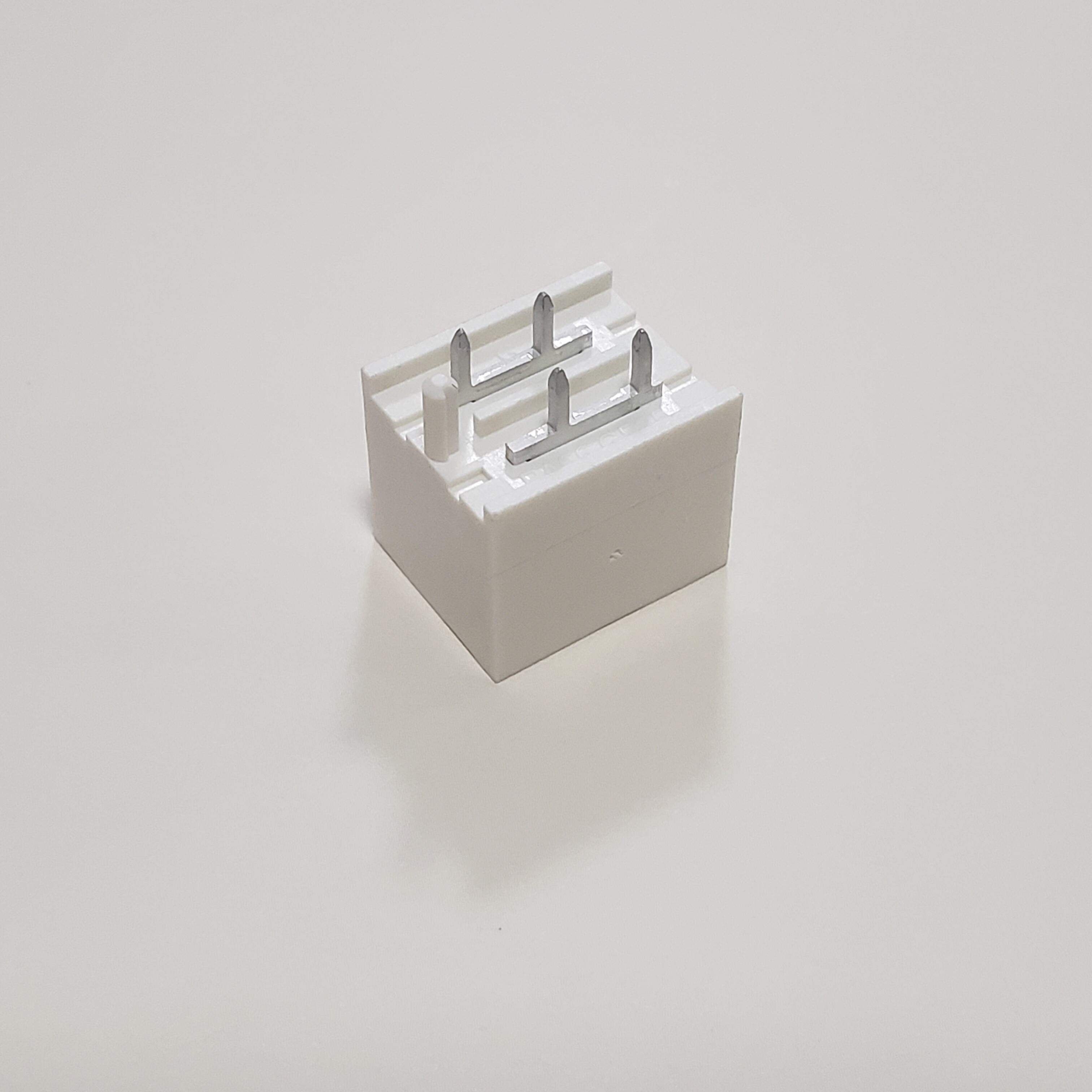
Selecting the right electrical terminals for your industrial or commercial project is a critical decision that directly impacts system reliability, safety, and long-term operational costs. Whether you are designing a control panel, assembling automation equipment, or wiring complex electrical distribution systems, the choice of electrical terminals determines how effectively your connections will perform under stress, environmental exposure, and continuous use. Many engineers and procurement professionals underestimate the complexity of terminal selection, focusing solely on price or immediate availability, only to encounter costly failures, maintenance issues, or compliance violations down the line. Understanding the key selection criteria—from current rating and wire compatibility to installation environment and certification requirements—enables you to make informed decisions that align with both technical specifications and project objectives.
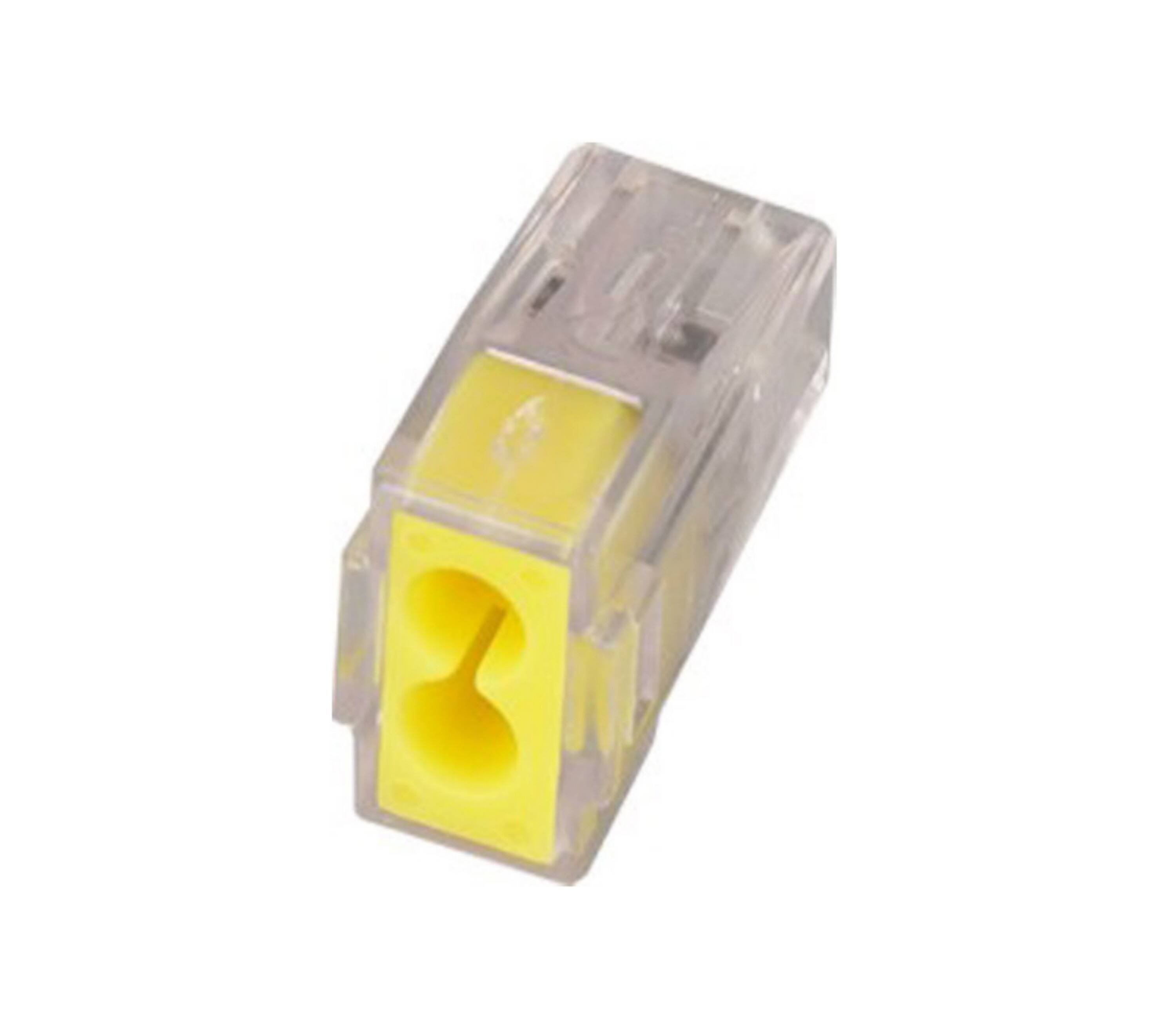
The selection process for electrical terminals extends far beyond simple connectivity. It involves analyzing electrical load requirements, understanding mechanical stress factors, evaluating environmental conditions, and ensuring compatibility with existing infrastructure. Industrial applications demand terminals that can handle high vibration, temperature fluctuations, chemical exposure, and moisture ingress, while commercial installations may prioritize ease of maintenance, space efficiency, and aesthetic integration. Furthermore, regulatory compliance with standards such as UL, IEC, and CE becomes non-negotiable in most jurisdictions, making it essential to verify that your chosen electrical terminals meet all applicable safety and performance benchmarks. This comprehensive guide examines the critical factors you must evaluate when selecting electrical terminals, providing actionable insights that help you balance technical performance, cost efficiency, and regulatory adherence across diverse project requirements.
Understanding Electrical Load and Current Rating Requirements
Calculating Maximum Current Capacity Needs
The most fundamental criterion when selecting electrical terminals is ensuring that the current rating matches or exceeds the maximum load your circuit will carry. Current rating, typically expressed in amperes, defines the maximum continuous current a terminal can safely conduct without overheating or degrading. Underestimating this requirement leads to terminal overheating, insulation breakdown, and potential fire hazards. When calculating your needs, you must account not only for normal operating conditions but also for startup surges, transient loads, and future system expansion. Industrial motor control circuits, for instance, may experience inrush currents several times higher than steady-state operation, requiring terminals with substantial derating margins to maintain reliability.
Professional engineers typically apply a safety factor of at least twenty to thirty percent above calculated maximum load when specifying electrical terminals. This margin accommodates unexpected load increases, ambient temperature variations, and aging effects that gradually reduce terminal performance over time. Additionally, you should consider whether your application involves continuous duty cycles or intermittent operation, as terminals rated for continuous use at a certain amperage may handle significantly higher currents during brief intervals. Understanding the distinction between continuous current rating and short-circuit withstand capability helps prevent specification errors that compromise system integrity.
Voltage Rating and Insulation Coordination
Voltage rating represents the maximum voltage that electrical terminals can safely isolate between adjacent circuits or between live parts and ground. This specification directly correlates with insulation material properties, creepage distances, and clearance dimensions built into the terminal design. Low-voltage applications below six hundred volts have different requirements compared to medium-voltage systems, and selecting terminals with inadequate voltage ratings creates serious arc flash and electrocution risks. The voltage rating must also account for transient overvoltages that occur during switching operations, lightning strikes, or fault conditions, which can momentarily exceed normal operating levels by several times.
Insulation coordination ensures that electrical terminals maintain proper electrical separation under both normal and abnormal conditions. This involves selecting materials with appropriate dielectric strength, designing adequate spacing between conductive parts, and incorporating pollution degree considerations that reflect the installation environment. Industrial environments with conductive dust, moisture, or chemical contaminants require higher pollution degree ratings than clean office settings. When evaluating voltage ratings for electrical terminals, verify that the specified values align with your system voltage, transient protection strategy, and the relevant safety standards applicable to your industry and geographical location.
Power Dissipation and Thermal Management
Every electrical connection generates heat due to contact resistance, and managing this thermal energy is crucial for long-term reliability. High-quality electrical terminals minimize contact resistance through optimized contact geometry, spring tension mechanisms, and conductive plating materials such as tin, silver, or gold. However, even the best terminals dissipate some power as heat, and this thermal load must be dissipated effectively to prevent temperature rise beyond rated limits. Excessive temperature accelerates insulation aging, increases contact resistance through oxidation, and can ultimately lead to connection failure or fire.
When selecting electrical terminals for high-current applications, evaluate the terminal's thermal characteristics including temperature rise curves, derating factors for enclosed installations, and heat dissipation capabilities. Terminals mounted in densely packed control cabinets or enclosed panels experience reduced cooling compared to open-air installations, requiring more conservative current ratings. Some terminal designs incorporate enhanced thermal management features such as increased metal mass, integrated heat sinks, or special mounting configurations that improve heat transfer to the DIN rail or mounting surface. Understanding how ambient temperature, mounting density, and enclosure ventilation affect terminal performance enables you to select components that maintain safe operating temperatures throughout their service life.
Wire Compatibility and Connection Technology
Wire Gauge Range and Conductor Types
Electrical terminals must accommodate the specific wire gauges and conductor types used in your application. Most terminals specify an acceptable wire size range, typically expressed in AWG for American markets or square millimeters for international applications. Attempting to terminate wires outside this range compromises connection integrity—undersized wire slots may damage conductors or prevent proper insertion, while oversized slots fail to provide adequate clamping force. When working with mixed wire sizes within a single project, consider whether your chosen electrical terminals offer sufficient flexibility to handle the full range or whether multiple terminal types become necessary.
The distinction between solid and stranded conductors significantly impacts terminal selection. Solid wire, typically used in permanent fixed installations, requires terminals designed to grip single-piece conductors without deformation. Stranded wire, common in applications involving movement or vibration, demands terminals that can compress the entire conductor bundle without individual strand damage. Some electrical terminals accommodate both conductor types effectively, while others optimize performance for one configuration. Fine-stranded or extra-flexible wire used in robotics and dynamic applications often requires ferrules or special terminal designs that prevent strand fraying and maintain consistent contact pressure over time.
Connection Methods and Installation Requirements
Connection technology fundamentally affects installation efficiency, maintenance accessibility, and long-term reliability. Screw-clamp terminals, the traditional standard, use threaded fasteners to compress conductors against a current bar or plate. They offer robust connections suitable for high-vibration environments but require proper torque application and periodic retightening. Spring-clamp terminals employ spring steel mechanisms to maintain constant contact pressure, eliminating the need for tools and reducing installation time by up to seventy percent compared to screw connections. These push-in terminals excel in applications requiring frequent disconnection or where technician skill levels vary significantly.
Insulation displacement connectors represent another category, piercing wire insulation to establish contact without stripping. This technology suits mass-termination applications but offers limited reusability. Crimp-style electrical terminals require specialized tooling but provide gas-tight connections resistant to vibration and thermal cycling. When evaluating connection methods, consider factors including installation time constraints, available tools, maintenance personnel capabilities, and whether connections will be permanent or require regular reconfiguration. Modern industrial projects increasingly favor tool-free electrical terminals that combine reliable performance with rapid installation, particularly in panel-building operations where labor costs significantly impact project economics.
Multi-Conductor Capability and Circuit Density
Space optimization becomes critical in compact control panels and distribution equipment where mounting area is limited. Multi-level electrical terminals stack multiple independent circuits vertically within a single mounting footprint, potentially doubling or tripling circuit density compared to single-level designs. This architecture proves particularly valuable in applications with numerous control signals, sensor connections, or parallel circuits that would otherwise consume excessive panel space. However, multi-level terminals introduce additional complexity in wire routing and may complicate troubleshooting efforts if circuit identification is not clearly maintained.
Bridge connectors and jumper systems enable efficient power distribution across multiple terminals, reducing wire count and installation time when multiple circuits share common potentials. Some electrical terminals integrate test points, disconnect functions, or indicator lights that enhance diagnostic capability without requiring additional components. When selecting terminals for projects with high circuit counts, evaluate whether modular accessories, labeling systems, and documentation features will simplify installation, commissioning, and future modifications. The optimal terminal selection balances circuit density with accessibility, ensuring that achieving space efficiency does not compromise serviceability or create safety hazards during maintenance activities.
Environmental Conditions and Protection Requirements
Operating Temperature Range and Thermal Cycling
Electrical terminals must function reliably across the full temperature range encountered in your specific installation environment. Standard terminals typically operate between negative forty and one hundred degrees Celsius, but specialized applications may require extended ranges for extreme cold storage, desert installations, or proximity to heat-generating equipment. Temperature affects both the mechanical properties of terminal housing materials and the electrical characteristics of contact surfaces. Plastics become brittle at low temperatures and may soften or deform at high temperatures, while metal contacts experience thermal expansion that can loosen connections or increase contact resistance.
Thermal cycling, the repeated heating and cooling experienced during operational cycles or day-night temperature variations, imposes mechanical stress on electrical terminals through differential expansion of dissimilar materials. This phenomenon gradually loosens screw connections and can create microscopic gaps at contact interfaces that increase resistance and accelerate oxidation. Applications with significant thermal cycling demand terminals with compensation mechanisms such as spring-loaded contacts or materials engineered to maintain consistent clamping force despite temperature fluctuations. When specifying electrical terminals for outdoor installations, HVAC equipment, or industrial processes with variable thermal conditions, verify that temperature ratings and material selections account for both steady-state and cyclic thermal stresses your application will encounter.
Moisture, Dust, and Ingress Protection
Environmental sealing capabilities determine whether electrical terminals can survive exposure to moisture, dust, chemical splashes, or high-pressure washdowns. The IP rating system quantifies protection levels, with the first digit indicating solid particle protection and the second digit specifying liquid ingress protection. Standard open terminals suitable for clean indoor environments typically offer minimal ingress protection, while sealed terminals designed for harsh environments may achieve IP67 or higher ratings that enable temporary submersion. Food processing, pharmaceutical manufacturing, outdoor installations, and marine applications all require elevated ingress protection to prevent premature failure.
Moisture infiltration creates multiple failure mechanisms including corrosion of metal contacts, insulation degradation, and the formation of conductive contamination paths that enable tracking or arcing. Dust accumulation, particularly conductive particles in metalworking or mining environments, can create short circuits or abrasive wear that damages contact surfaces. When selecting electrical terminals for challenging environments, consider not only the terminal body protection but also how cable entry points, mounting interfaces, and potential condensation paths might compromise sealing integrity. Some applications benefit from conformal coating treatments, sealed terminal compartments, or the use of terminals specifically engineered with gaskets and sealed housings that maintain protection throughout the product lifecycle.
Chemical Resistance and Corrosion Protection
Chemical exposure from process fluids, cleaning agents, atmospheric pollutants, or nearby industrial operations can rapidly degrade electrical terminals constructed from incompatible materials. Terminal housing plastics must resist attack from solvents, acids, alkalis, oils, and other chemicals present in the installation environment. Common engineering plastics like polyamide offer good general chemical resistance, but specialized environments may require fluoropolymers, polysulfone, or other advanced materials. Metal components including contact springs, current bars, and mounting hardware also require appropriate protection through plating, coatings, or material selection.
Corrosion protection strategies for electrical terminals vary based on the corrosive agents present and the required service life. Tin plating provides economical protection for mild environments and maintains good solderability. Nickel plating offers enhanced corrosion resistance particularly against sulfur-bearing compounds and humidity. Gold plating, while expensive, delivers superior corrosion resistance and low contact resistance for critical signal applications. Stainless steel hardware prevents rust in wet or corrosive atmospheres where standard steel fasteners would quickly deteriorate. When evaluating chemical resistance requirements, obtain material compatibility data specific to the substances your terminals will encounter and verify that all components—not just the housing—provide adequate protection for your service environment and expected operational lifetime.
Standards Compliance and Safety Certifications
International Electrical Standards and Testing Requirements
Regulatory compliance represents a non-negotiable aspect of electrical terminal selection for professional installations. Multiple international and regional standards govern terminal design, testing, and application including IEC 60947, UL 1059, and various industry-specific requirements. These standards establish minimum safety criteria covering electrical performance, mechanical durability, flammability resistance, and environmental capability. Products certified to these standards have undergone rigorous third-party testing to verify compliance with safety requirements, providing assurance that terminals will perform as specified under normal and fault conditions.
The certification landscape varies significantly by market and application sector. North American installations typically require UL or CSA certification, European markets demand CE marking with applicable directive compliance, and many countries mandate additional national certifications. Industrial machinery applications may require specific functional safety certifications such as IEC 61508 for safety-instrumented systems. Railway, marine, and hazardous location applications carry specialized certification requirements beyond standard industrial certifications. When selecting electrical terminals for projects with defined regulatory requirements, verify that the complete certification package addresses all applicable standards and that certification markings remain current and cover your specific terminal configuration including any accessories or modifications.
Safety Features and Fault Protection Capabilities
Modern electrical terminals increasingly incorporate safety features that reduce installation risks and enhance protection against common fault conditions. Touch-proof designs prevent accidental contact with live parts during maintenance operations, particularly important in energized equipment servicing scenarios. Some terminals integrate disconnect or isolation functions that enable circuit interruption without wire removal, facilitating safer troubleshooting and testing procedures. Finger-safe designs meet IP20 requirements preventing standard test probe insertion into live terminals, an essential safety feature for equipment accessed by non-electrical personnel.
Ground fault protection capability depends on proper grounding terminal selection and placement. Dedicated protective earth terminals typically feature enhanced mechanical security, green-yellow identification, and design characteristics that ensure ground connections remain intact even if phase connections fail. Circuit identification features including integrated test points, LED indicators, and clearly marked polarity improve diagnostic capability and reduce troubleshooting errors that might create hazards. When safety considerations are paramount, prioritize electrical terminals with built-in protective features that create multiple barriers against common failure modes and installation errors rather than relying solely on procedural controls and training.
Documentation and Traceability Requirements
Comprehensive technical documentation enables proper terminal selection, correct installation, and effective long-term maintenance. Quality manufacturers provide detailed datasheets specifying all electrical ratings, mechanical dimensions, material compositions, environmental capabilities, and certification details. Installation instructions should clearly explain proper wire preparation, insertion techniques, torque specifications, and any special handling requirements. Some regulated industries including aerospace, medical devices, and nuclear power require complete material traceability and manufacturing documentation that enables verification of component provenance throughout the supply chain.
Product marking facilitates field identification during installation and maintenance activities. Clear terminal identification including manufacturer name, model number, and key ratings enables verification that installed components match design specifications. Some electrical terminals incorporate QR codes or RFID tags that link to electronic documentation, simplifying specification confirmation and reorder processes. For projects requiring extensive documentation such as public infrastructure, pharmaceutical facilities, or safety-critical systems, verify that your terminal supplier can provide certification packages, test reports, material declarations, and traceability documentation that satisfy project-specific quality assurance and regulatory submission requirements.
Practical Selection Strategy and Long-Term Considerations
Total Cost of Ownership Analysis
Effective terminal selection extends beyond initial purchase price to encompass total cost of ownership across the complete product lifecycle. While economy terminals may reduce upfront expenditure, they often generate higher costs through increased installation labor, elevated failure rates, and more frequent replacement requirements. Premium electrical terminals with tool-free connection technology can reduce installation time by fifty percent or more, translating to substantial labor savings in large projects despite higher component costs. Reliable terminals with proven longevity minimize unplanned downtime, reduce maintenance labor, and avoid the secondary costs of production interruptions or service failures.
When evaluating total cost, consider factors including expected service life under actual operating conditions, availability of replacement parts, compatibility with future system expansions, and whether terminal selection constrains or enables efficient panel modifications. Standardizing on a limited range of high-quality electrical terminals across multiple projects reduces inventory complexity, simplifies maintenance training, and improves spare parts management efficiency. Some applications justify premium terminals with enhanced features based purely on reliability benefits, while others appropriately employ economy solutions where accessibility permits easy replacement and failure consequences remain minimal. A thorough lifecycle cost analysis incorporating all relevant factors typically reveals that mid-range to premium terminals deliver superior value despite higher initial investment.
Supplier Reliability and Technical Support
Supplier selection significantly impacts long-term success with electrical terminals beyond the inherent product quality. Established manufacturers with proven track records offer greater assurance of consistent product quality, stable specifications across production batches, and long-term product availability that simplifies future additions or replacements. Technical support capabilities including application engineering assistance, custom solution development, and responsive problem resolution distinguish premium suppliers from commodity vendors. Access to training resources, design tools, and comprehensive product documentation accelerates project execution and reduces specification errors.
Supply chain reliability affects project schedules and inventory management strategies. Manufacturers with global distribution networks and substantial inventory positions minimize lead times and reduce supply disruption risks. Supplier financial stability and commitment to continued product support matter particularly for capital equipment projects with extended service horizons where terminal availability over decades becomes important. When selecting electrical terminals for critical applications or large-scale deployments, evaluate supplier capabilities across quality consistency, technical support responsiveness, supply chain reliability, and long-term business viability rather than focusing solely on product specifications and current pricing.
Future-Proofing and System Flexibility
Anticipating future requirements during initial terminal selection provides valuable flexibility for system modifications, capacity expansions, and technology upgrades. Modular terminal systems that accept various accessory components including surge protection modules, signal conditioning elements, and communication interfaces enable functional enhancement without replacing base terminals. Terminals with generous wire size ranges accommodate circuit modifications or load increases without terminal replacement. Adequate spare capacity in current ratings and physical panel space prevents situations where minor changes require complete panel rebuilding.
Industry trends toward increased automation, remote monitoring, and digital integration influence terminal selection for forward-looking projects. Some modern electrical terminals incorporate features supporting Industry 4.0 initiatives including sensor integration, power monitoring capabilities, and communication interfaces for predictive maintenance systems. While not every project requires cutting-edge functionality, understanding available technologies and designing infrastructure that can adopt advanced capabilities as needs evolve provides long-term value. Balancing current requirements with reasonable future flexibility ensures that your electrical terminal selection serves immediate project needs while avoiding premature obsolescence that forces costly upgrades or workarounds as systems evolve.
FAQ
What is the difference between current rating and short-circuit withstand capability for electrical terminals?
Current rating specifies the maximum continuous current an electrical terminal can safely conduct under normal operating conditions without exceeding temperature limits, typically expressed in amperes for a given ambient temperature. Short-circuit withstand capability indicates the maximum fault current the terminal can survive for a brief period, usually one second, without mechanical or electrical failure. This rating addresses abnormal conditions where protective devices have not yet cleared a fault. Terminals must be rated adequately for both continuous operation and the worst-case fault currents available in your electrical system based on upstream protection device characteristics and available short-circuit current at the installation point.
How does installation environment affect electrical terminal selection beyond basic temperature and moisture considerations?
Installation environment influences terminal selection through multiple factors including vibration levels that may loosen screw connections requiring spring-clamp alternatives, altitude effects that reduce dielectric strength necessitating voltage derating, pollution degree affecting creepage and clearance requirements, UV exposure degrading plastic housings in outdoor applications, electromagnetic interference requiring shielded terminals for sensitive signals, and accessibility constraints determining whether tool-free terminals are necessary for maintenance efficiency. Chemical exposure, biological growth potential, vermin intrusion, and mechanical impact risks also factor into comprehensive environmental assessment that extends well beyond simple temperature and humidity specifications.
Can I mix different terminal types and manufacturers within a single control panel?
While technically possible, mixing electrical terminal types and manufacturers within a single panel creates complications including inconsistent mounting dimensions that waste space, varied color coding schemes that confuse circuit identification, different accessory compatibility limiting design flexibility, and increased inventory complexity for spare parts. Professional practice favors standardizing on a single terminal series from one manufacturer for each voltage level and application type throughout a panel or facility. This approach optimizes space utilization, simplifies documentation, reduces training requirements, and streamlines maintenance operations. Exceptions may be justified for specialized circuits requiring unique capabilities unavailable in the standard terminal family, but such deviations should be minimized and clearly documented.
What maintenance do electrical terminals typically require over their service life?
Screw-type electrical terminals require periodic retorquing, particularly after initial installation when wire compression settles, and subsequently at intervals determined by vibration exposure and thermal cycling severity, typically annually for industrial environments. Spring-clamp terminals generally require no routine maintenance beyond visual inspection for housing damage or wire degradation. All terminals benefit from periodic thermographic inspection to identify developing hot spots indicating loose connections or excessive resistance. Harsh environments may necessitate periodic cleaning to remove conductive contamination and inspection of seals or gaskets for degradation. Terminals exposed to significant vibration should be inspected more frequently, while critical circuits may warrant periodic contact resistance measurement to verify connection integrity before problems develop into failures.
Table of Contents
- Understanding Electrical Load and Current Rating Requirements
- Wire Compatibility and Connection Technology
- Environmental Conditions and Protection Requirements
- Standards Compliance and Safety Certifications
- Practical Selection Strategy and Long-Term Considerations
-
FAQ
- What is the difference between current rating and short-circuit withstand capability for electrical terminals?
- How does installation environment affect electrical terminal selection beyond basic temperature and moisture considerations?
- Can I mix different terminal types and manufacturers within a single control panel?
- What maintenance do electrical terminals typically require over their service life?

